

Application of Passive Wireless Temperature Measuring Device in Transformer
Category: Company News
Category: Industry News
2018-05-29
Temperature is one of the key parameters of transformer operation, real-time monitoring of transformer temperature can effectively prevent accidents and ensure the safe and stable operation of transformer equipment. Researchers Zhu Jianhua, Liang Dong, Li Fang, Zhai Haiwen and Feng Linna, from Xi'an West Variable Components Co., Ltd., wrote an article in the first issue of Electrical Technology magazine in 2020, proposing a passive wireless temperature measurement device.
The research results show that the antenna of the device has excellent performance at 433MHz operating frequency, and can monitor the temperature change of the transformer safely and effectively for a long time, so as to avoid the potential safety hazard of the transformer caused by the high operating temperature of the transformer, and provide technical guarantee for the safe operation of the transformer.
With the rapid development of the scale of the national power industry, the demand for electricity continues to rise, and power transformers continue to develop in the direction of large capacity and high voltage. As an important power equipment in the power system, the safety and reliability of the transformer will have a direct impact on the power supply quality of the power grid. Power transformer faults mainly include thermal faults and electrical faults, of which overheating faults account for about 63% of the total number of faults. Therefore, the effective implementation of on-line monitoring of transformer temperature is of great significance to ensure the safe and stable operation of the transformer.
On the whole, the current temperature measurement methods can be divided into two types: regular detection and real-time online temperature measurement. Among them, the way of regular detection is mainly infrared detector and through the preventive test of the power outage temperature measurement, these two ways have the problems of large workload, low efficiency, can not detect the temperature in real time.
From the point of view of the way to take electricity, the online temperature measurement can be divided into active temperature measurement and passive temperature measurement. Among them: the active temperature measurement method has the infrared camera temperature measurement method, which uses the infrared imaging principle for real-time temperature detection, but the cost is very high; the passive temperature measurement sensors mainly include platinum thermal resistance temperature sensor, optical fiber temperature measurement sensor, surface acoustic wave temperature measurement Sensor and inductive electric temperature sensor, etc.
In passive temperature measurement sensors, platinum thermal resistance temperature sensors use cables for signal transmission, and the temperature signals are greatly affected by the environment. The optical fiber temperature measurement sensor uses optical fiber as the transmission signal line, and the temperature measurement accuracy and data transmission quality are higher than those of platinum thermal resistance temperature sensors, but the optical fiber core is easy to break during installation and the cost is higher. Surface acoustic wave temperature measurement sensor uses the principle that the spectrum absorbed by some substances changes with temperature, analyze the spectrum of optical fiber transmission to understand the real-time temperature, but there is a shortcoming of short transmission distance. The induction temperature sensor can only work normally after the induction current is greater than a certain value, and there is a problem of limited application range.
In view of these problems, this paper proposes a transformer temperature measurement device based on passive wireless sensor technology, which uses passive wireless technology and thermoelectric power generation technology to realize on-line monitoring of transformer temperature, which can detect abnormal transformer temperature in time and prevent transformer accidents.
1 thermoelectric power generation theory (omitted)
Under the temperature gradient, the carriers in the P-type semiconductor and the N-type semiconductor move from the hot end to the cold end and accumulate at the cold end, thus forming a potential difference inside the material. At the same time, a reverse charge flow is generated under the action of the potential difference. When the thermal charge flow and the internal electric field reach dynamic balance, a stable temperature difference electromotive force is formed at both ends of the semiconductor, which is called Seebeck effect. The schematic diagram of the structure of the thermoelectric power generation device is shown in Figure 1.
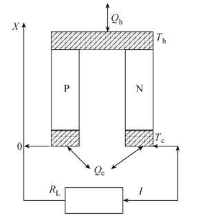 Fig.1 Schematic diagram of thermoelectric power generation device structure
The core device of the device is a thermoelectric generator, and the two sides of the thermoelectric generator are cold end and hot end respectively. After the temperature difference between the cold end and the hot end of the thermoelectric generator reaches a certain level, the thermoelectric generator converts heat into electrical energy, and supplies power to the device itself after subsequent circuit processing.
A schematic diagram of a thermoelectric generator unit module is shown in Figure 2. A plurality of thermoelectric conversion units are combined into a whole by means of series connection, parallel connection or a combination of both. Through the thermoelectric generator unit module, the thermoelectric generating device converts the generated heat into electric energy, that is, the thermoelectric conversion can be realized.
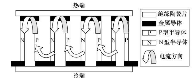 Fig.2 Schematic diagram of thermoelectric generator unit module
2 Signal transmission theory (omitted)
2.1 Wireless Signal Transmitter Impedance Matching Theory
According to the impedance matching theory, when designing a wireless signal transmitting antenna, the load impedance and input impedance in the transmission line circuit should meet the conjugate matching condition to obtain the maximum signal power, so as to achieve the best signal transmission performance.
Design of 2.2 Wireless Signal Transmitter
The wireless signal transmitter designed by the temperature measuring device is a 433MHz miniaturized spiral printed antenna. The antenna uses microstrip lines in the upper and lower two layers of crosstalk of the dielectric substrate to imitate the trace form of the spiral antenna.
In the design of the spiral printed antenna, the upper and lower routing ends of the antenna are connected through a copper hole with a radius of 0.35mm. This connection method can not only effectively reduce the space occupied by the antenna wiring, but also increase the physical length of the antenna circuit path.
In addition, considering that electromagnetic interference exists between the upper-layer antenna and the lower-layer antenna and a gain attenuation phenomenon caused by current traces having different directions between the upper-layer antenna and the lower-layer antenna, the dielectric substrate between the upper-layer antenna and the lower-layer antenna can also effectively improve the gain characteristic thereof.

这里是标题一h1占位文字

Business contact:
Mr. Wu: 15322054255
Miss Wang13827769412
Huarui Service Phone:0757-87653135
Enterprise E-mail:
Company Address:
Block 7, No.5, Lequn Avenue, Liping Town, Sanshui District, Foshan City


